How I Configured X-Plane Screens For The Basement Sim

First, I’m writing this quite quickly as I have someplace I need to be. So forgive any typos, and I may revise it a bit later …

After several days of tweaking I finally have my X-Plane 11 visuals for the Basement Sim where I like them, and I like them a lot. It was a bit of a process getting there, and absolutely a learning experience as I’ve never played in this space in X-Plane before, but it was fun and I feel like I understand it much better – and I really like the results.

You’ll remember that the reason I had to do all of this is because of how X-Plane handles multiple monitors. Historically, it didn’t do this at all without significant add-ins. With X-Plane 11, though, we have multi-monitor support, and it works great, thanks to a simple dialogue that allow you to set a field of view (the default is 60 degrees), along with lateral, vertical, and roll offsets for that field of view. In essence, if each monitor is like a camera on a tripod, you can set the width of the image (field of view), as well as the direction it is pointing horizontally (lateral), tilt (vertical), and side-angle tilt (roll).

So by setting different offsets for each camera, you should be able to achieve a set of views where the front screen is looking out the front of the airplane, the left screen is looking straight out the left window, and the right screen is looking straight out the right window. By varying the fields of view, which act like a zoom, you should be able to get objects on different-sized monitors (I have a 100 inch projection screen in front and 32 inch LEDs on the sides) to match up. And finally, by varying offsets, you should be able to get the horizon to match up across the three screens.

After some trial and error, I was able to do this. For my screens and my cockpit, this was the setup that worked best:

LEFT SCREEN:

  • 57 degree FOV
  • -90 lateral offset
  • – 6.5 vertical offset
  • 0 roll offset

FRONT SCREEN:

  • 97 degree FOV
  • 0 lateral offset
  • 7 vertical offset
  • 0 roll offset

RIGHT SCREEN:

  • 57 degree FOV
  • 90 lateral offset
  • -6.5 vertical offset
  • 0 roll offset

These settings produced a nice alignment of horizon and runway lines that matched up very well, especially from the position of the GoPro in the back middle of the cabin. But there was a problem, and the problem was that I could still see the panel on the front screen. So just use the arrow keys to raise the eye point, right? But therein is the complication, because in X-Plane 11 (at least so far) the multiple views are all connected to a single eye point, meaning that they all move together. So when I raised the view to get the panel out of the way, the top of the virtual cabin windows were now in view. And if I lowered the view to get the windows out of the way, the panel was visible. Everything moves together. So how to solve THAT problem?

The answer is the great little program that comes with X-Plane, Planemaker.exe. It allows you to make your own aircraft for the sim, or to modify the ones you fly. You can find it in the same root directory in which X-Plane sits. It turns out that the airplane models in plane maker are made of three-dimensional objects that the designer loads to cover the wireframe (and invisible) physical dimensions of the airplane and flight model. In essence, they design a wireframe airplane, and then fill and cover it with textures and objects, like wings. These objects don’t affect the flight characteristics, as they are simply window dressing for the flight model. And it turns out that you can move them around, and even delete them entirely. The airplane will look different–if you delete the wings and look at the airplane in chase view, it will have no wings–but it will still fly just fine.

It’s because of this that I was able to solve my view problem of having a panel that was too high, wings that were two low, and cabin walls that I could see. Here’s how I did it, with some screen grabs from my Mac which has X-Plane 10 on it (this Cessna looks a bit different than the one in X-Plane 11, but you’ll get the idea):

  • In my X-Plabne “Aircraft” folder I made a duplicate of the default Cessna 172 folder. I created a full copy called “Cessna 172SP Copy” that had all the contents of the original in it. This way I could work without messing up the original.
  • The file that Planemaker reads is a .acf file. I opened plane maker, and opened the Cessna_172SP.acf file from the Copy folder. When you do, you’ll see something like this:

Screenshot_12_14_16__4_43_PM

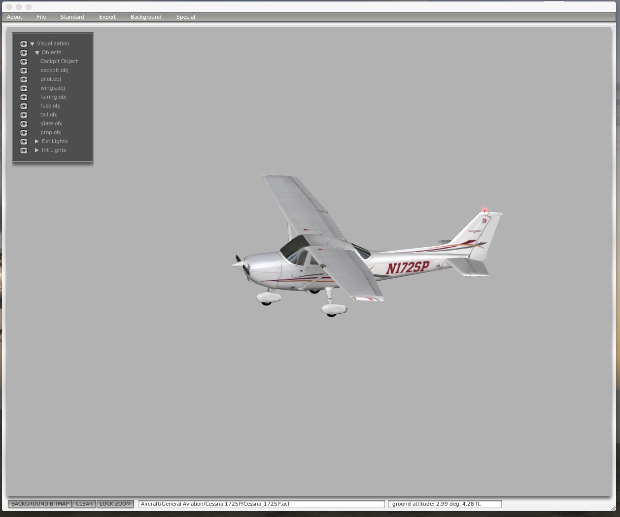
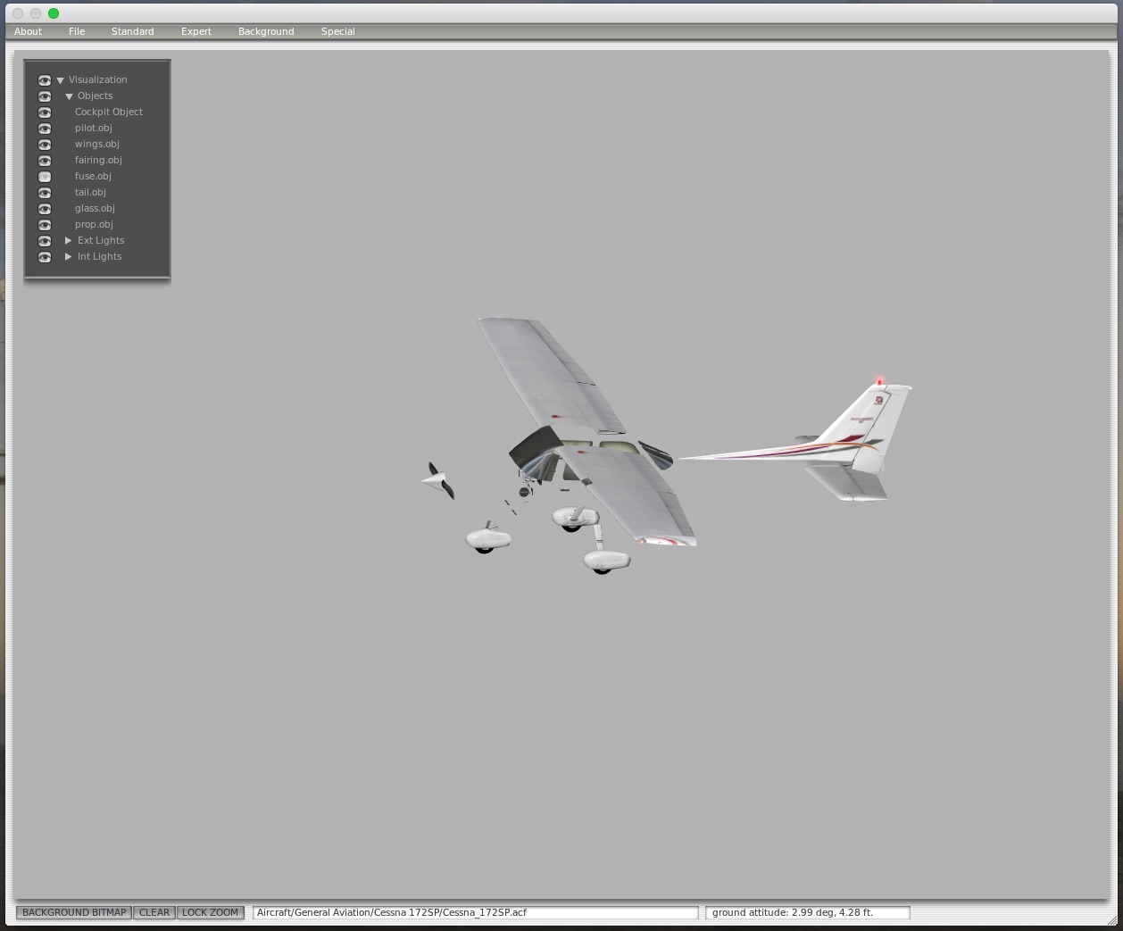
  • With the Visualization menu on the left you can “turn on” or “turn off” different parts of the visual model. This does NOT make them invisible in the sim – it just makes them invisible so you can see what’s behind them. Here’s a view where I’ve turned off the fuselage object:

Screenshot_12_14_16__4_46_PM

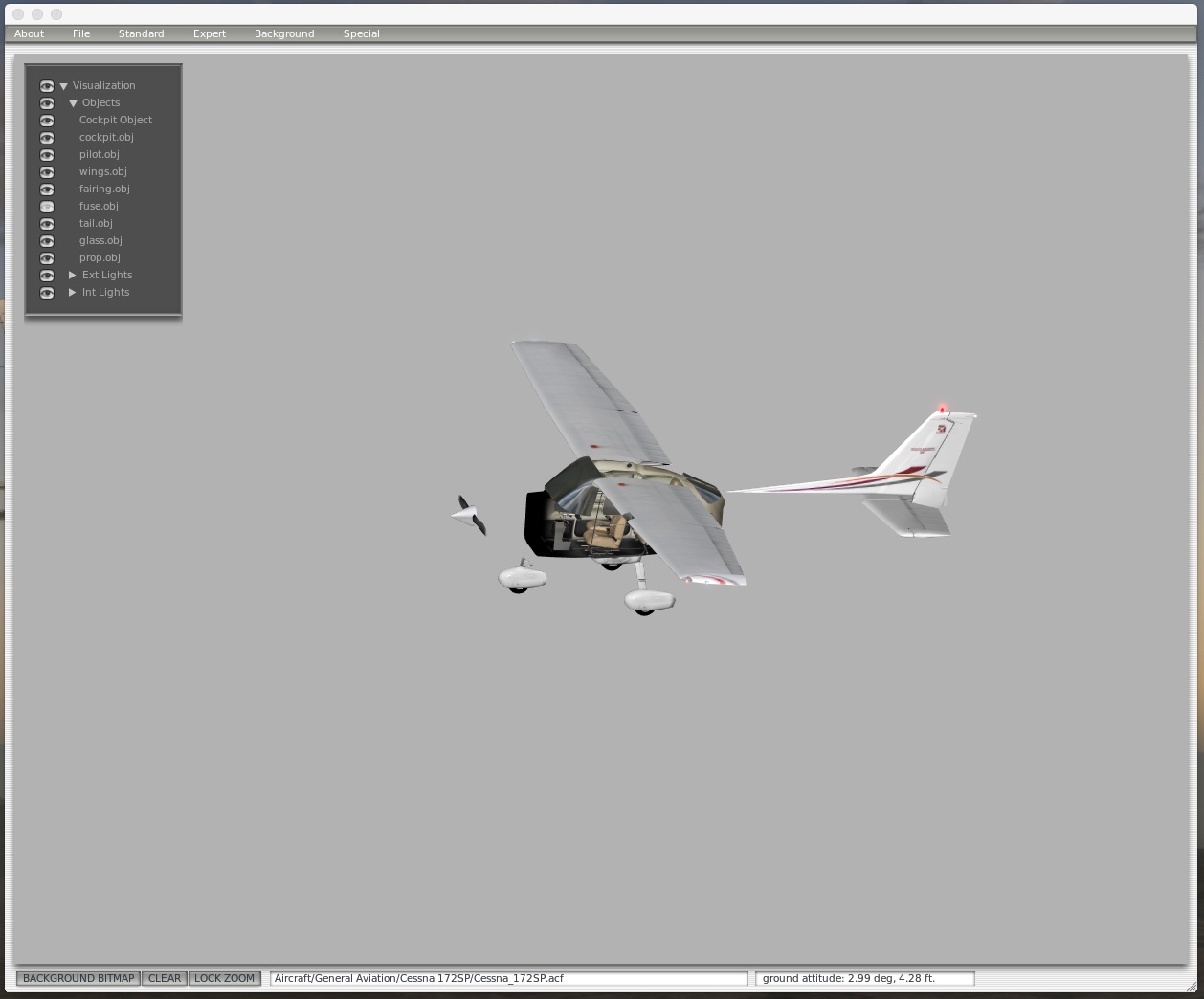
  • Turn off the fuselage object so it’s out of the way. Then click Standard / Misc Objects from the menu. You will see a screen that lists all the 3-D objects that make up the visual model of the airplane. something like this:

Screenshot_12_14_16__4_47_PM

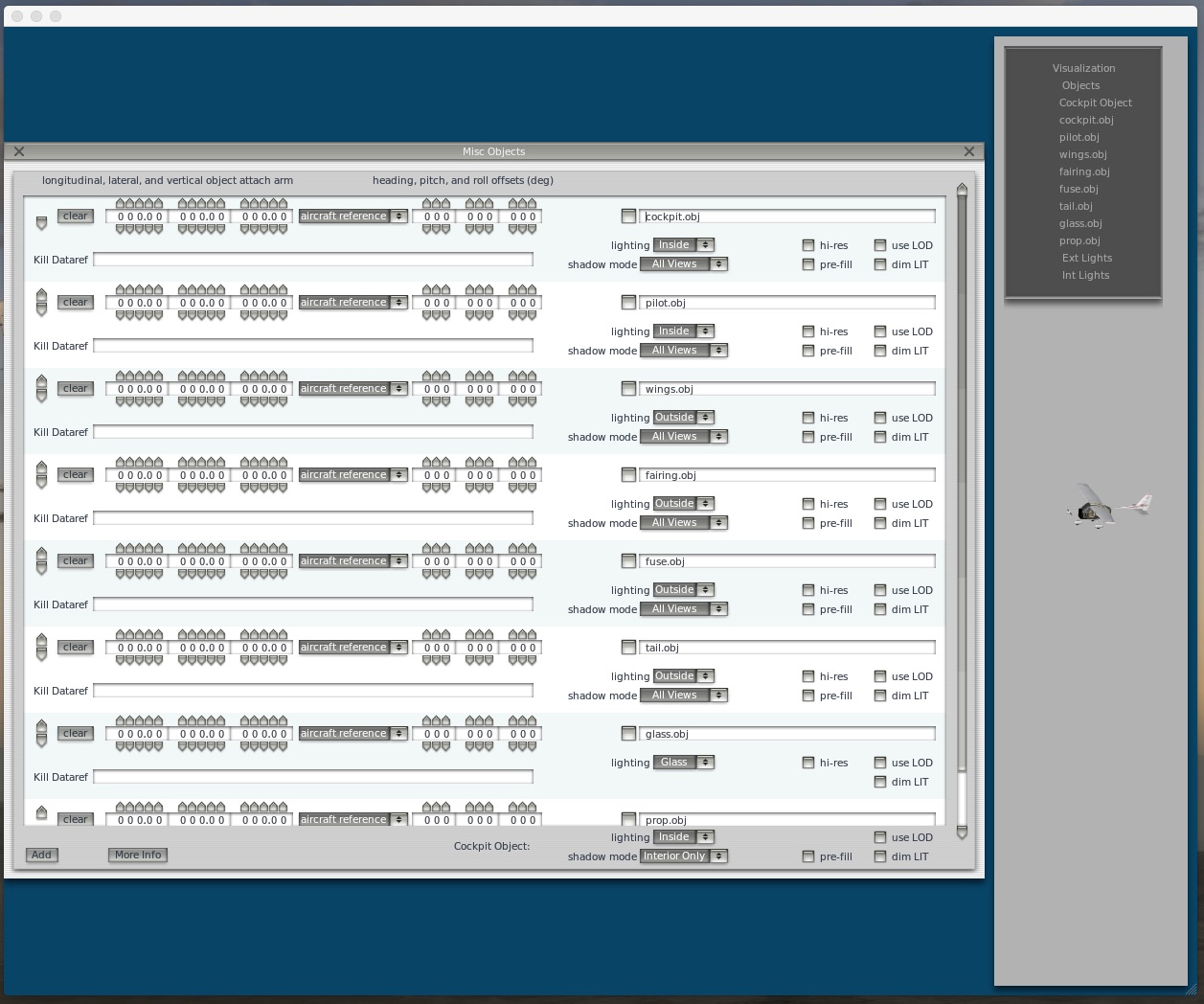
  • This is a powerful screen, so tread lightly here. But if you click the “clear” button for any of the objects, Planemaker will delete them from the visual model. They won’t show up in the sim at all, but it also won’t affect the flight model. Your external screenies may look strange, but you can easily remove things you don’t want to see. If I delete the cockpit.obj object, the model now looks like this:

Screenshot_12_14_16__4_49_PM

  • So that’s what I did. In the X-Plane 11 172 I also deleted a second cockpit object, seats, and a bit more. I DID NOT delete any of the avionics or panel, because I think they may need to be in the model to work, but I’m not sure. When I loaded X-Plane 11 and loaded that Cessna (if you look at the details for the airplane in the flight setup screen it will show you which folder it’s in so you can pick the correct one from the Copy folder), I could see the wings, cowl, and prop, but the cockpit was gone, and I finally had a correct view like I was looking out real windows. BUT – there were still alignment problems (wings too low, cowl too high, panel too high).
  • If you look at the Misc Objects screen you will also see that you can adjust the vertical, lateral, and horizontal positioning of objects, and you will actually see them shift around on the screen. I used this to lower all the panel objects a lot (but still so I could see them by tiling my view in case I needed to), to lower the cowl and prop a bit, to raise the wings a bit (I suppose I could have just raised them and left the cowl in place, but I’d already moved it), and to move the wings forward.
  • Finally, I adjusted the starting eye point so that every time I load that airplane the view is in the right place: in the center of the aircraft, rather than in the pilot’s seat, and a bit forward so the wings are just where I wanted them (again, If I moved the wings more I could have accounted for this there, but not the center position of the view). You can tweak this in Planemaker as well, using the Standard/Viewpoint window. It looks like this (this is the X-Plane 10 version, and the 11 is just a bit different):

Add_New_Post_‹_On_The_Glideslope_—_WordPress_and_Cessna_172SP

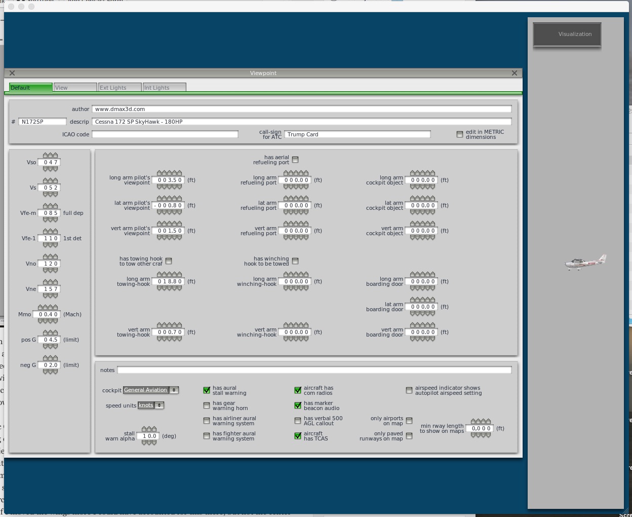
  • By adjusting the “pilot’s viewpoint” values you alter the starting location of the view when you open a flight with the plane. I adjusted the lateral value to 0, which starts the camera right in the center of the cabin, and moved it forward a bit by adjusting the longitudinal arm (long arm) value DOWN to be about 2.2 feet. This starts the sim with the view just where I want it, and the whole thing now looks like this:

DCIM106GOPROGOPR7006.

DCIM106GOPROGOPR7005.

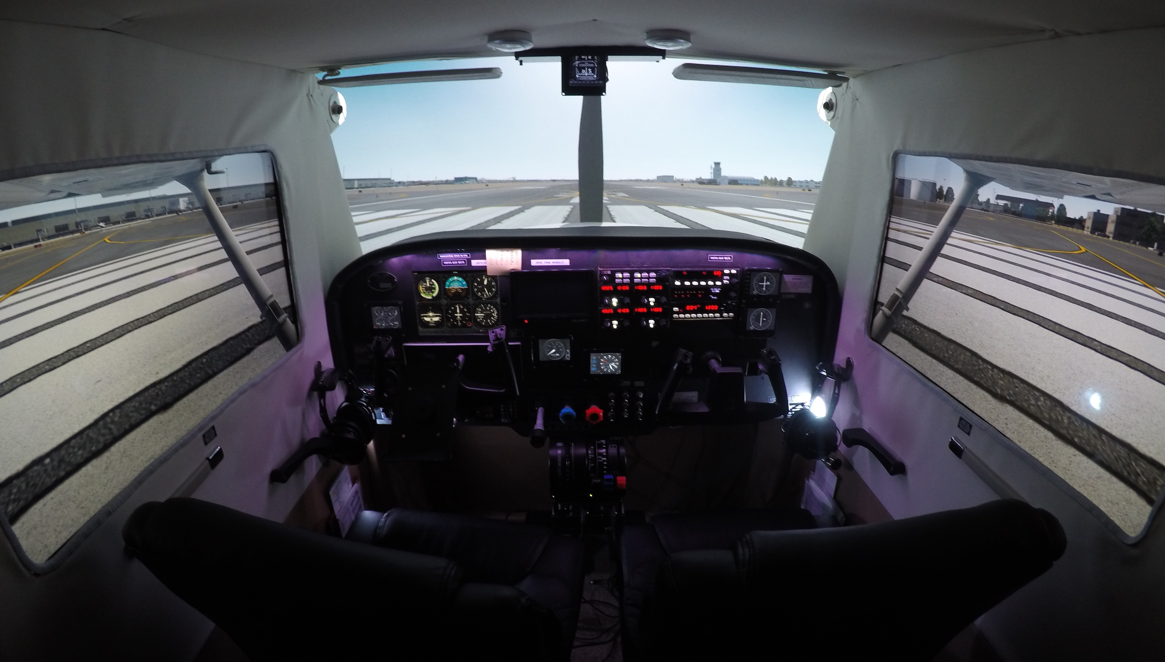
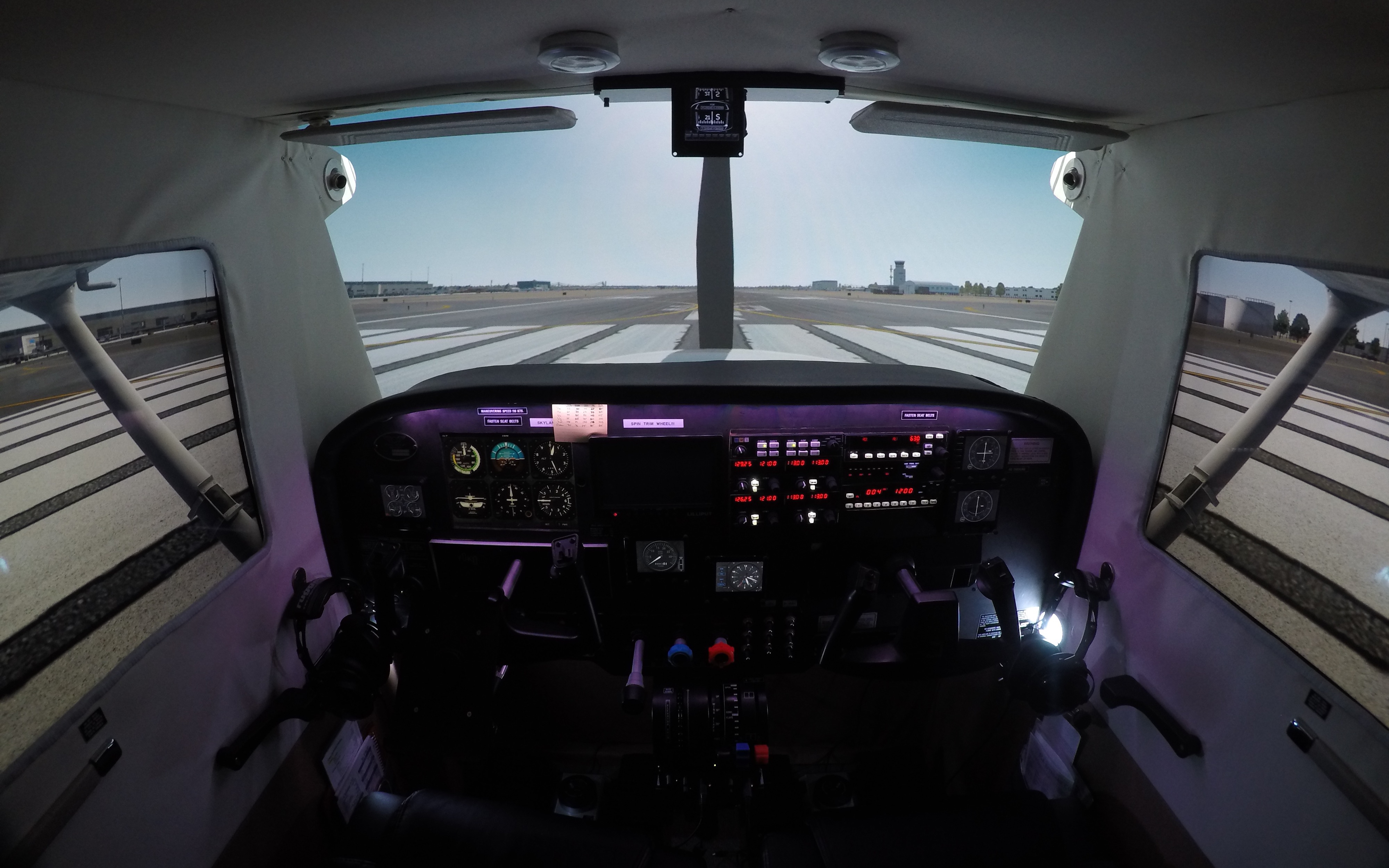
And I think that looks pretty good. So, with all this behind me, when it’s time to do this for a new aircraft I believe I’ll do the following:

  • Configure the screens first, probably using the “no scenery, no HUD” view so I can just focus on getting the sizing and alignment correct.
  • Then look in the 3D cockpit view to see how things interrupt with the view, and to move the eye point around to get a sense of what I need to delete and move.
  • Use Planemaker to delete objects.
  • Go back into X-Plane to see how it looks and to decide if I need to adjust the wings, etc., then go back and forth with Planemaker until I have those adjustments how I like them.
  • Use Planemaker to get the permanent starting eye point where I want it.

I actually don’t think that will take very long, now that I’ve done it once. Of course, If Laminar allows unique eye points for each screen, all this will be unnecessary. Until then, I hope it’s of help to you, and that it helps many more X-Plane simmers build their own cockpits. To help with that, you may download my .acf file for the 172 here. It probably won’t be perfect for your sim, but it might be a good starting point. Thanks for reading.

My Custom Camera Configurations

One of the most common questions I get about the basement sim is how I’ve aligned the cameras across the side LEDs and the front projection screen. I wrote a post about the process here, but a few folks have still asked for the config files themselves. I’ve actually written the camera settings into the individual configuration files for each aircraft I fly, but I do keep a reference file that has the settings. I’ve pasted it below the “continue reading” break below.

But please remember: these settings are based on the aircraft in the sim, the width of my cabin, the size of my screens, and the distance and height of my projector. Your mileage may vary considerably. Also, note that the first several camera settings below are in the format you need to add a custom camera to a scenario file, and the final one (for the Piper 180) is in the format you need to add a camera view to an aircraft config file. Hope this all helps.

Continue reading “My Custom Camera Configurations”

How To: Creating Custom Cameras In Prepar3d V3 (Especially For Three-Monitor Setups)

How To: Creating Custom Cameras In Prepar3d V3 (Especially For Three-Monitor Setups)

Many of the questions I get on my YouTube channel are about my screen setup and how I manage to get the images on the projector and side screens to align. I do it through custom cameras created using the custom camera tool in Prepar3d, and thought it might be helpful if I wrote a post here explaining my process.

There are two ways you can use custom cameras in P3D. One is to create new camera views in a particular scenario. These will be saved in the scenario config file (which is stored in the P3D folder in your PC’s Documents folder), and they will be persistent with that scenario: whenever you load it, those camera views will be listed as options in the Custom Camera submenu of the View menu at the top of the screen. If you save custom cameras in your default scenario, they will remain there, too. The other is by adding them to an airplane’s default configuration file, in which case that camera view will always be available for any scenario or flight with that airplane. That’s a bit more complicated. I’ll describe both here.

Creating custom views is easy but not always intuitive, and through (much, much) trial and error, I’ve learned ways to simplify the process and get good alignment across multiple screens. Here’s my process for setting up a new set of screen views, which for me would involve three cameras: Front (for the projection screen and view out the front of the aircraft), Left (for the view out the left window), and Right (same for the right window).

FIRST: I begin with the front view, because it’s the front horizon that I will want the side views to match up with. Custom cameras inherit the settings of the view from which they start, so to save time I first use the view directional keyboard commands to move the view to something close to what I want to have (forward / back, left / right, up / down). It’s easier to tweak a view that’s sort of close than to start completely from scratch.

SECOND: I right click on the front view select “Custom Camera / Create New” from the popup menu:

Photo May 15, 8 53 57 AM

This brings up the Manage Camera Views screen:

Photo May 15, 8 54 29 AM

THIRD: I tweak that view to get it to my liking, and the easiest way to do this is to use previews. Click the Preview button, and it will open a new view window on the main screen that has inherited the view from which you clicked. Drag the window and its edges so it fills the front view screen. From now on any changes that you make to the variables in the Manage Camera Views dialogue will show instantly on that view screen when you click the Preview button. So you can easily tweak, preview, tweak, preview, etc.

As for the variables in the dialogue, here’s what they mean:

  • X is the placement of the eye point left or right of center in the aircraft
  • Y is the placement of the eye point above or below center in the aircraft
  • Z is the placement of the eye point front or back of center in the aircraft
  • Pitch is how “nose up” or “nose down” the view is
  • Bank is how angled left or angled right the view is
  • Heading is how turned to the left or turned to the right the view is

Tweak these settings until the view is how you like it, then give it a name in the dialog and click “Save.” P3D will then ask you if you want to quit or not. If you choose “Yes” the dialog will close as will the preview window, but a view with that name will now appear in the Custom Camera pop-up menu, and you can select it for your front view. With my front view is that I like to see the cowling of the aircraft, but not the glare shield (as my sim has one). This means my front view is pushed forward quite a bit along the Z axis, and yours may be different.

FOURTH: Once the front view is created, I make a left-hand view for the left window monitor. I follow the same process as above, using the keyboard keys to turn the view to the left, move it close to the window, adjust the height, etc. Again, I’m just trying to get it close. Once it is, I open the Manage Camera Views dialogue, create a preview, drag it over to the left window monitor, fill the screen, and begin tweaking the preview. One variable that I simply set rather than tweak is the Heading variable. For the Left view I set it to -90, as this has me looking directly out the left side of the aircraft.

Through trial and error I’ve learned two things are important with the side views. The first is that at least for me, the side views and front view need different zoom settings. My sim is really close to the projection screen, and it’s a 100-inch screen. To keep objects from being huge I have the front zoom at .30. For objects on the side views to be about the same size they need a greater zoom, and I use .60. I’ve come to this through trial and error, and in my sim this has things like the buildings and taxiway lines matching up well from a size perspective. Your zoom settings will be different, but know that the front and side views may need different zooms. The second is that the Bank variable is important. The default camera views nearly always have the horizon when viewed out the side window tilted toward the front or rear of the aircraft. I use the Bank variable to adjust the tilt to make the horizon straight, and the Pitch variable to adjust the height of the horizon so it lines up with the horizon of the front view across the two screens. This may take some trial and error, and might mean re-tweaking the front view’s Pitch a bit, but when it’s dialed in I can (1) see the cowling of the aircraft out the front, (2) see the bottom of the wing and my flaps out the side, and (3) have the horizon match up across both left and front screens.

When I have the left view correct I save it with the name “Left,” and instead of quitting the Manage Camera Views dialogue I click “No” because I want to continue with the next view: Right.

FIFTH: Once I have my Left view I do NOT close the Manage Camera Views dialogue. Instead, I rename the view Right, and keep all the variables THE SAME except three: X, Bank, and Heading. Bank and Heading are easy: just make them the inverse version of the Left value (so if the Bank and Heading were -4.5 and -90 for left, they should be 4.5 and 90 for right). Y, Z, Pitch, and Zoom should stay the same. This ensures your Left and Right views are mirror compliments of each other. The only variable to tweak is X, as it’s how far left or right of center the eye point is. For the Right view you’ll want it up close to the right window, so I tweak that variable, looking for a point where the both the left and right struts (or wings for a low-wing airplane) seem about the same size and position. Then I save that view as “Right” and close the dialogue.

At this point you should have three saved camera views, Front, Left, and Right, and you can assign them to their respective views and monitors. Now the question is how to keep them for use in other flights. I have two ways of doing this. First, and easiest, is to add the camera views you’ve defined to other saved scenarios. To make this easy (and to back up my work) I’ve created a text file on my desktop called “Cameras” into which I’ve pasted my camera settings so they are backed up and easily at hand. This is easy to do: go into the Documents/Preapar3d folder on your PC and open in a text editor the scenario .CFG file in which you created your custom views. Scroll down and you will see the standard camera views, and below that your custom ones. Just copy and paste the code into your backup Cameras file. Here’s a screen shot of part of mine:

Screenshot 2016-05-18 15.42.17

I have camera setups for four aircraft: the Carenado 182, A2A 182, A2A 172, and A2A Piper 180. All are pasted into this backup file so I have them. Then I can copy and paste the appropriate camera code into the config file of any particular scenario without having to create the camera views via the dialogues. Just open the scenario config file in a text editor and add the appropriate camera code at the bottom of the pre-existing camera locations. Just be sure to continue numbering the camera setups consecutively within the file.

You might also want your camera setups to be part of a default aircraft configuration, so those views are available whenever you start a flight with a particular aircraft (saved scenario or not). This is a little more complicated, but not much so. Let’s say I want to add my the A2A 172 Front / Left / Right camera setups to the default A2A 172 so they are always available whenever I use that aircraft. To do this I would go into my P3D directory / simobjects / airplanes / A2A 172 subdirectory and open the airplane .CFG file in a text editor. If you scroll down in an airplane .CFG file you will find the camera definitions, and they look like this:

Screenshot 2016-05-18 15.43.43

As you can see, these look DIFFERENT than the scenario camera definitions, which is where people get confused. The good news is that there are only a few lines of code that you need to change to convert one of these default views into a custom camera view. Here’s how to do it.

  • First, copy an existing camera definition within the airplane .CFG file. It doesn’t matter which one.
  • Second, paste it at the end of the camera definitions, and give it a new cameradefinition number that is next in the sequence from the definition above it.
  • Third, change the Title variable of the view to the name you want (e.g, “A2A 172 Front”).
  • Fourth, change the InitialZoom variable to be the correct zoom for your custom camera.
  • Fifth, change the InitialXyz line to reflect the X Y Z values from your custom camera.
  • Fifth, change the InitialPbh line to reflect the Pitch, Bank, and Heading values from your custom camera.
  • Sixth, and last, go to www.guidgenerator.com  and grab a GUID number. Each camera needs a unique identifier, and this site will give you one. Paste it OVER the GUID value between the brackets at the top of the camera definition. When you’re done, it should look something like this:

Screenshot 2016-05-18 15.44.08

Save the file. That’s it, unless you want to add Left, Right, or other views, in which case you can repeat the process.

In terms of having this all look good from a REAL camera’s perspective if you’re filming with a GoPro etc., what I’ve learned is key is that the camera be at about the same height as your eyes in your simpit. Then everything should line up across the three monitors as they do from where you sit (with some minor variability).

I hope this is helpful.